Description
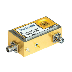
DRO-1000 Series Dielectric Resonator Oscillator (DRO) utilizes state of the art MIC to provide highly stable,
reliable and efficient signal source at microwave frequencies up to 50 GHz. The low profile and rugged
construction provide excellent durability against harsh environmental conditions.
DRO-1000 oscillator is designed using FET or BJT amplifier with series feed back at source and Dielectric
Resonator at the gate. High gain, low-noise FETs/BJTs are biased positively or negatively at the gate to ensure
minimum phase-noise. The devise is carefully matched for maximam power, minimum phase-noise and Voltage
Standing Wave Ratio (VSWR). The oscillator is matched for maximum temperature stability and optimum
negative resistance.
DRO-1000 oscillator is buffered by cascaded low-noise driver and power amplifiers for minimum load pulling,
maximum isolation and power. FET/BJT devices are directly attached to gold plated Kovar carriers to minimize
shear effect and maximize heat sinking. Kovar carriers are mounted to the chassis to provide an efficient
thermal junction and a stable structure for reduction of microphonics. To ensure oscillator stability over the full
temperature range, the tuning elements are precisely designed and positioned to compensate for temperature
drift by a factor of three.
DRO-1000 series provides several advantages over other microwave signal sources, such as Gunn Cavity
Oscillators and Crystal Multiplier Chains.
DRO-1000 series is internally voltage regulated to avoid reverse bias. frequency pushing, bias modulation
and voltage transients. Mechanical frequency adjustment is provided for optimum phase voltage setting.
APPLICATIONS:
* SATELLITE COMMUNICATIONS
* CABLE TV LINKS (CATV)
* LOCAL AREA NETWORKS (LAN)
* GLOBAL POSITIONING SYSTEMS (GPS)
* TEST EQUIPMENT
* POINT TO POINT
* UP/DOWN CONVERTERS
* TRANSMITTER & RECEIVERS
* DIGITAL RADIOS
* MISSILE GUIDANCE
* SPACE, MILITARY, COMMERCIAL